REMEHA Quinta 85 Technical Information
Browse online or download Technical Information for Fireplaces REMEHA Quinta 85. REMEHA Quinta 85 Technical information User Manual
- Page / 68
- Table of contents
- BOOKMARKS
- Remeha Quinta 85 1
- 00.W4H.79.00044 13
- 04.W4H.79.00002 33
- Flue outlet 35
- Air inlet 35
- -controller 41
- 04.W4H.79.00009 43
- 00.W4H.79.00005 51
- 00.W4H.79.00019 55
- Fig. 25 Quinta 85 63
Summary of Contents
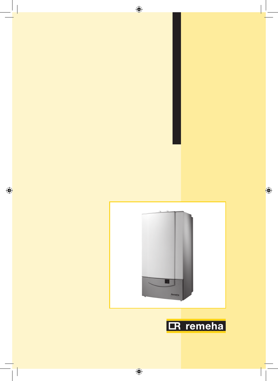
Remeha Quinta 85• High-efficiency condensing boiler for wall mounted installation• Output: 14 - 90 kWTechnical informationRemeha Quinta 85
Remeha Quinta 85103.2 Technical dataBoiler type Quinta 85GeneralColour side and front casingColour instrument panel flapBS RAL90167036Boiler control o
11Water contents ltr 7.5Water resistance at 11 °C dt mbar 460Water resistance at 20 °C dtmbar 140Nominal flow at 11 °C dtl/s 1.74Nominal flow at 20
Remeha Quinta 85123.4 Options - Floor frame.- Two pipe flue/air inlet adapter plate (excentric room sealed).- DHW-sensor.- Weather compensating cont
136 CONTROL AND SAFETY EQUIPMENT6.1 The control panel6.1.1 GeneralThe boiler is supplied with a standard set of defaults pre-programmed for normal o
Remeha Quinta 8514a. ‘code’-displayIndicates on user level:operating mode: only one digit 1setting mode: digit with dot !read-out mode: digit with fla
15‘s‘-key and r-symbol:- (symbol) not illuminated: HTG under normal control- red (symbol) on: HTG off (manual override) ‘e’-key and k-symbol: - (sy
Remeha Quinta 85166.2 Flow diagram control systempress the ‘m’ -key press the ‘s’-key‘code’-displaytdisplayOperating mode, see Par. 6.3only digit or
17En/aFn/aGForced part load time after start (HTG)HFan speed at startIDHW control stop or boiler modulation set point (based on parameter #)JDHW contr
Remeha Quinta 8518service engineer level only:Speed mode, see Par. 6.8alternate half digit <Fan speedFailure mode, see Par. 6.9flashing digit1Failu
19bShut-off modehForced full load.lForced part load.Table 04 Operating codes6.4 Shut-off mode (bXX)During shut-off mode condition the code-display wi
Remeha Quinta 852TABLE OF CONTENTPreface 51 General description of the boiler 62 Construction 72.1 Boiler layout 72.2 Operating principle 83 Te
Remeha Quinta 8520NOTE: Shut-off mode is a normal boiler operating function and does not represent a boiler failure.However, this may indicate a syste
216.5.1 Flow temperature set point (!)The required flow temperature is adjustable from 20 to 90°C (factory default 80°C).Fig. 04 Typical setting cha
Remeha Quinta 85226.5.3 DHW temperature set point (3)The DHW temperature is adjustable from 20 to 75°C (factory default 55°C). Only with Broag DHW p
23t-displayDescriptionSecond segment [yOperation mode0HTG and DHW off 1HTG and DHW on 2HTG on and DHW off 3HTG off
Remeha Quinta 8524*Modulation start point dt (F/R)05 - 30 ºC 25(Interface selection (control option)00 internal (Chronotherm control only)0101 exter
25QStart point for 0 Volt analog signal 5) (= -50) – 50 °C 00YEnd point for 10 Volt analog signal 50 – (( (=299) °C)0 (=100)*_Intern10Table 09 Settin
Remeha Quinta 85266.6.6 Interface selection (()Adjustable 00 or 01, factory default 01 This value sets the control option. 01 for standard 0 -10 Volt
27Parameter H factory set must not be changed6.6.10 DHW control stop set point (I)Adjustable from 00 - 30 °C factory default 20°C.Refer to Par. 6.6.7
Remeha Quinta 8528End point (10 Volt): adjustable between +51°C and (( (+299)°C, factory default )0 (100)°C.This value sets the required flow temp at
29Code Description Example 5250 r/m,Fan speed 52 hundreds>Fan speed50 unitsTable 11 Fan speed mode service level 6.9 Failure mode (x00)To check
36.6.6 Interface selection (() 266.6.7 DHW cut-in temperature (B) 266.6.8 Fan Speed at DHW full load (C) 266.6.9 Forced part load time after start
Remeha Quinta 85307 INSTALLATION INSTRUCTIONS7.1 General The complete installation must comply with the current editions of relevant British Standards
317.3 Flue gas discharge and air supply7.3.1 GeneralThe Remeha Quinta 85 is suitable for conventional room ventilated or room sealed operation. Speci
Remeha Quinta 85327.3.2 Classification due to discharging flue gases Classification according to CE:Type B23: Conventional room ventilated boiler wit
337.3.3 Material and installationFlue gas discharge: Rigid single walled: stainless steel (316), aluminium or plastic (to comply with building regula
Remeha Quinta 8534Quinta 85100 mmmaximum Length L m 24eq. Length bend 45° m 1.4eq. Length bend 90° m 4.9Table 13 Calculation data conventional flueE
35Quinta 85100/150 mmmaximum Length L m 13eq. Length bend 45° m 1eq. Length bend 90° m 2Table 14 Calculation data room sealed applicationsExample: Qu
Remeha Quinta 8536The Remeha Quinta boiler (twin connection only) is capable of operating with the air inlet and flue outlet in different pressure zon
377.4.2 Water treatmentThe system should be filled with mains cold water (for the UK this will usually have a pH of between 7 and 8).Pressurised insta
Remeha Quinta 8538To Summarise:- Minimise water loss- Prevent pumping over in open vented systems- Provide adequate air venting at all high points-
397.4.5 Gas connectionConnect the boiler to the incoming gas in accordance with the requirements of the Gas supply company. Install the main gas cock
Remeha Quinta 8548.3 External connections 438.4 Boiler control 448.4.1 Modulating (two wire control) 448.4.2 Analog control (0 -10 Volt dc) 468.
Remeha Quinta 8540Fig. 10 Remeha Quinta with calorifier and DHW pump04.W4H.HS.00002Flow and return header installationA flow and return header instal
41Fig. 11 A flow and return header installation with rematic® -controllerpdf
Remeha Quinta 8542T0020158 ELECTRICAL INSTALLATION8.1 GeneralThe Remeha Quinta 85 is supplied as standard with electronic control and flame ionisation
438.2.4 Boiler temperature controlThe Remeha Quinta 85 has electronic temperature control with flow and return temperature sensors. The flow temperat
Remeha Quinta 8544Fig. 14 Electronic components.pdf1. Screws instrument panel2. Terminal strip3. Cable clamp 4. Display5. Interface for 0 -10 V contr
45- Celcia 20 - An optimising/ weather-compensated boiler control for single boilers. This compensator can regulate the boiler output against outside
Remeha Quinta 8546Fig. 16 Fitting the interface05.W4H.79.000088.4.2 Analog control (0 -10 Volt dc)The heat output modulates between the minimum and
47Fig. 17 Ratio between voltage and temperaturepdfOnInput voltage VFig. 18 Ratio between voltage and outputpdf8.4.3 On / of
Remeha Quinta 85488.4.4 High / low control (2 x no volt switched pairs)The heat output is controlled between part load (18%, adjustable) and full loa
498.9 Safety interlock As standard the boiler is supplied with an interlock carrying a 24 Volt boiler control circuit. To use first remove the fitted
5PREFACEThese technical instructions contain useful and important information for the correct operation and maintenance of the Remeha HTG boiler, mode
Remeha Quinta 85509 COMMISSIONINGNOTE: Engineer to carryout pre-commissioning checks to ensure that the installation complies with current regulations
5115. Re-establish power supply to boiler and isolate controls.16. Use manual override to start the boiler (press and hold for 5 seconds[-]-key (gree
Remeha Quinta 8552Fig. 21 Flue gas measure point.05.W4H.79.00004Boiler modelGas typeFan speed(approx. rpm)O2CO2full load part load % %Quinta 85Natura
5319. Remove flue gas analyser and seal test point; also remove manometer and re-tighten test nipple and test for soundness. 20. Simulate a lock
Remeha Quinta 855410 FAULT-FINDING10.1 General (all installations)Check the following, in sequence (by service engineer):Step Signs Check points Actio
556 Only with rematic® SR 5240 C1 or 2945 C3 K control: Check the communication between control and boiler by means of the two LED’s on the interface,
Remeha Quinta 8556Code Description Cause/check points and remedy0) Flame simulation- Gas valve shuts but burner surface continues to glow due to inco
570*Setting failure- check parameter D (second digit must be 0)1!Failure of internal communication bus- short circuit in flat cable: replace flat cab
Remeha Quinta 8558Fig. 21 Sensor resistance graph pdfFig. 22 Ionisation measurement04.W4H.79.00007
5911 INSPECTION AND SERVICING INSTRUCTIONS11.1 GeneralThe Remeha Quinta 85 has been designed to need minimum maintenance, but to ensure optimum effic
Remeha Quinta 8561 GENERAL DESCRIPTION OF THE BOILERThe Remeha Quinta 85 is a wall hung condensing boiler which may be also installed free standing o
Remeha Quinta 8560Fig. 24 Sensor resistance graphpdf11.3 MaintenanceIf during the annual inspection combustion results indicate that the boiler is no
61NOTE: connect rear electrical plug on fan before final positioning when re-fitting5. Remove M5 retaining nuts securing venturi to front plate6. Re
Remeha Quinta 856211.9 Cleaning/replacing the ignition/ionisation electrodeRemove the two retaining screws on the electrode assembly, remove assembly
6311.11 Part list Quinta 85 boilerEVGBW4H085001b/07.0477124268282423739431323958625474725033526125184716201389163651748564951713379707041432828294483
Remeha Quinta 8564Part description Pos nrCasing side left + right 1Flue gas pipe Ø 100 mm. 3Screw cap measure point flue gas pipe 4Adapter plate Ø 100
65O-ring gas pipe Ø 26.8 x 22 x 2.5 41Return pipe 42Flange for gas combi-block 43Sealing plate (siphon black foam) 44Support bracket air inlet 46Wash
© CopyrightAll technical and technological information contained in these technical instructions, as well as any drawings and technical descriptions f
72 CONSTRUCTION2.1 Boiler layoutFig. 01 Boiler layout Remeha Quinta 85 pdf 1. Automatic air vent2. Air supply fan 3. Gas combi-block (with g
Remeha Quinta 8582.2 Operating principleCombustion air is drawn into the closed air box by a variable speed fan, through the air inlet connection from
93 TECHNICAL DATA AND DIMENSIONS3.1 DimensionsFig. 02 Dimensions Remeha Quinta 8500.W4H.79.00048 + 05.W4H.79.00024Ê Return connection 1¼” BSP (m)É
© 2020, manymanuals.com. All rights reserved. | 1.033 s |
 Manymanuals.com
 Manymanuals.de
 Manymanuals.fr
 Manymanuals.it
 Manymanuals.pl
 Manymanuals.cz
 Manymanuals.es
 Manymanuals-pt.com
Comments to this Manuals